• Thanks for stopping by. Logging in to a registered account will remove all generic ads. Please reach out with any questions or concerns.

AN/PRC-522 Manpack long wire antenna ?

Evocatus

Guest
Inactive
Reaction score
0
Points
60
Old signallers and old para signallers in particular will recall the home made modified long wire antenna modification that we used to use with the AN/PRC-25 Set and later it's cousin the AN/PRC-77 Set, to extend the range, by either:
  a. tossing it up into the trees to jack it up 2-30 ft vertical; or
  b. employing as a long wire, extended along the ground, in the desired direction of propagation.

It, simply worked wonders, increasing range.

As a retired signaller, I recall as the IRIS/TCCCS AN/PRC-522 Manpack, replaced the 77 Set, it was neigh impossible to 'make' a similiar long wire for the 522, as there were " impedance issues " [not experienced with the ancient 77 set].

Question: has anyone since come up with a way to att a home made long wire to the 522 overcoming said aforementioned issue ?

Much Thx.    V.V.V.
 
 
Apparently it's the same drill; use a coax, stripping away the braided shielding, to bare the center conductor to 1/4 wavelength [freq X 234], including accommodation for a loop at the end [for lanyard to hoist up].

Leave the BNC connector on the radio end and hook it up.

One cannot connect the radio end to the AN/PRC-522 [like we did to the 77 set] as it will balk at the 'home made' antenna, not recognize it as legit and thus you can hit the presso swt all you want.....nothing.

problem very simply solved.
 
211RadOp said:
234/freq in MHz

Those of us in the civilized world use the λ(m)=300/ƒ(MHz)

Much cleaner, 1/2 wave is 150/ƒ, 1/4 wave is 75/ƒ

Plus metric is what you need to use if you are going to start to delve into the science of radio.
 
Question: has anyone since come up with a way to att a home made long wire to the 522 overcoming said aforementioned issue ?

I bet AN/PRC-25 didn't give a HOOT about impedance because it used tubes instead of transistors. Happily dumping it's energy to a mismatched antenna.  Why it worked with the prc-77, I don't know.
New radios are built with transistors and expect an impedance of approx 50 ohms. 


Other people in this thread:
Apparently it's the same drill; use a coax, stripping away the braided shielding, to bare the center conductor to 1/4 wavelength [freq X 234], including accommodation for a loop at the end [for lanyard to hoist up].
Leave the BNC connector on the radio end and hook it up.
λ(m)=300/ƒ(MHz)
One person says Lambda = 300/F

*I will do my test at 35MHz*
1/4 wavelength with  λ(m)=300/ƒ(35MHz)  = 2.1428 meters for a quarter wave.

Lets try the other formula provided.
234/freq in MHz = 6.6857  (I am going to assume feet)..... HOLD ON JUST A HOT SECOND! Thats 2.037 meters. Where the hell did my ~10 centimters go? And are they important?
Where are these formulae from? Why the difference? I must find the answer!
With a little duckduckgo-fu, I found I am not the only person to search for this:
https://www.eham.net/article/23802
It's answered in the link above way better than I could type it out.

My question becomes for VHF frequencies is the difference important?
Especially with army coax and wd-2.

I don't own any army coax, I have RG-58 and RG-213 and all the parts and connectors came out of my pocket.
I do have a ferrite core from an antenna "matcher" that all the other pieces were destroyed by weather and impact. I tried it in these experiments by winding one turn of the coax through it  but there was no noticeable change.
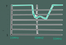
[PICTURE 1]
I took a 84Inch piece of wire hung from some paracord. The paracord was over a tree branch to raise and lower it. I then connected the 84 inch vertical antenna wire to the center of a ~150cm piece of coax.
I raised the radiating wire untill it was off the ground by a few inches.
Then I check to see if it was on frequency. It was way too low! (25MHz!) (I double checked my 84 inches at this point).
I kind of expected a poor result because I did not provide a ground plane for the antenna to work off of.
I added a random length of "ground" wire (hooked on to where the coax splits) [PICTURE 2]  and the resonant frequency increased a couple MHz.
No significant change by earth grounding the ground (shield of the coax).
I trimmed the antenna at least 40 cm before it would get close to a match,
This was the closest it got by trimming the antenna 3 cm at a time:
[Picture 3]

Absolute failure,
Absolute garbage, this will not match the radio at all! An SWR of 3 is army serviceable. Under 2 is where it should be IMO.
What went wrong? I'm sure I measured the radiating element right.
I will do further experiments as time permits.


End goal:
Create a decent formulae for an omnidirectional field antenna that will just work®
Answer the first posters question about long wire antennas.

I was reading the https://www.marines.mil/Portals/1/Publications/MCRP%208-10B.11.pdf?ver=2017-03-15-092827-423
and I see that the vertical portion is shown to be used as a replacement for a broken antenna.  Not as a vertical whip attached from a short piece of coax near the ground.
All the other field expedient antennas are proper dipoles connected to a length of coax.
That will be my next test.
 

Attachments

  • swr.png
    swr.png
    43.2 KB · Views: 76
Not a Sig Op said:
"army coax" for small radios is just RG58.

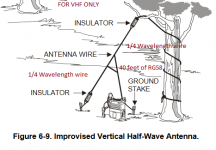
Because of your comment, I fished out 40 feet of RG58, added a connector and took it to the field to test the half-wave vertical as described in the US Field Antenna Manual (as linked above).
Results to follow (because  I don't know how to attach multiple images ).
 

Attachments

  • half-wave vertical.PNG
    half-wave vertical.PNG
    42.9 KB · Views: 110
So I took the 234/MHZ = 1/4 wavelength formula to get = 6.68 feet or 6 feet, 8.2 inches for each radiating element.

I used a gerber to measure out the wire and then I cut two equal lengths.

I connected the coax to the testing unit.

The other end of the coax I split into shield and center conductor. I connected the shield to 1/4 wavelength wire and the center conductor to 1/4 wavelength wire.

I tried to keep the split apart wires of the coax as short as possible.
Around 1/2 inch.

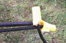
Then I used wire nuts from the hardware store to connect the coax to each wire.
I had to remove some of the plastic from the wire nuts to get it to fit and make a good connection.
 

Attachments

  • theconnector.png
    theconnector.png
    372.3 KB · Views: 80
I then threw a rope over a tree limb and raised the antenna vertically.

The MP's rolled up!
They asked what I was doing, I explained. I poured out my wobbly pop. They checked it out and then left. I heard them say as they got in the car "I've never seen anything like that before" AHAHAAHAHA

So the antenna was raised. 1/2 foot under the branch supporting it (by nylon rope) and it was a couple feet off the ground.
The antenna was not touching any branches or foliage.

There was a small hook of wire (~1.5 cm) to hold the wire to the rope for support at the top.  Nothing at the bottom, it was left hanging.

Edit:
It was only light sprinkles, not proper field conditions.
Not enough rain and mud.
If you deploy something like this you'll want to water proof the braid. Use silicon from the mechanics or the EO techs. Failing that, jam some chewed gum into the braid going in to the coax.

Why? The water will suck in to the braid and cause it to fail over a few days/ weeks.  It won't hurt the radio. But what will happen is the power will be absorbed by the coax and turned in to heat. The more power turned in to heat, the less is radiated.

Maybe make a poncho for the connector with a ration pack plastic or wrapping?
 

Attachments

  • antennaintree.jpg
    antennaintree.jpg
    147.8 KB · Views: 76
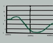
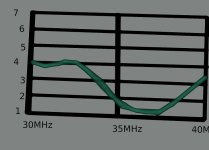
The results!
See attached picture!

Very usable! But it's a little high in frequency to be optimum.

Did I mess up in length? I used my gerber to cut it at 203.6 CM..... being a gerber bodge job... I actually cut it at:
199.39CM (Plus or Minus 1 CM) :facepalm:
Too short of wire results in it being at too high a frequency. I also made a hook out of the top of the antenna (2.5cm).  So if you plan to hang the wire from the top, cut it an inch or 1 1/2 inch longer.  Or use gun tape on the wire itself.
 

Attachments

  • swrwithoutchoke.jpg
    swrwithoutchoke.jpg
    77.7 KB · Views: 72
I tried adding a "Dirty Choke" or "Air choke" or "Dirty coil" as described by the us mil manual.
I took 7 turns around a diameter aprx the size of a canteen.
I used rope to keep it in place.

Not a huge difference, but it kept the tuning from changing when the ground/ radio was touched at the operator side.

A very worthwhile/ easy addition for making sure you have more power radiated.
 

Attachments

  • swrwithchoke.jpg
    swrwithchoke.jpg
    62.6 KB · Views: 66
Boy, you guys are amateurs.

Try dragging almost six kilometres of antenna behind you to get your E.L.F. signal, like ballistic submarines do, or used to do anyway [that, BTW, was a quarter wave antenna].

;)
 
Smaller antennas, smaller margins for error :P  JK,  that's pretty cool.  I couldn't imagine an ELF antenna, Must have been huge!

So, I knew my antenna was too high in frequency. I figured I would add some inductance to bring it down. I have successfully used this on HF to get a too short dipole in tune with empty 1L water bottles as forms.

Just for fun...
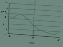
On the top and bottom wire 1/4 way away from the center I wrapped the wire around a fairly dry stick the diameter of three pencils four times. I expected the working frequency to drop... instead....


Attachments

  • swr with inductor.jpg
    swr with inductor.jpg
    15.1 KB · Views: 72
What was learned:
The formula for feet is ok, add an inch or inch and a half to be safe. IMO


You shouldn't take a length of coax 1/4 wavelength long from the radio, then use the exposed center conductor to make up the rest of the antenna.... it just doesn't radiate well.  At the minimum, have a length of coax multiple wavelengths long. No matter the type of antenna.

Some wire is better than no antenna at all.

Knowing this, I'm confident if I have to make an antenna in the field.

The next step, answer the first post about matching a long wire to a vhf set. (I'd be happy with any directionality)
Edit
I have work at least 12 hours each day for at least the next couple days, so it might be a bit before I can get back on.
 
As long as youre geeking out, you can pick up small snake head on ebay or amazon for a couple of dollars (BNC to banana jack), rather than using wire nuts.

Can get one  with either a male or female BNC connector.

Pro-tip, if you're crimping a new BNC connector on, slip a 3/8 piece of "dual walll" heat shrink on to the cable first, and shrink it on over crimp barrel after.

Dual-wall is basically heat shrinked lined with hot glue,  does a good job helping to keep water out, and also does a really good job reinforcing the connector.

Dual wall and coax crimpers can be had cheap too.
 
In the previous posts by setting up a good dipole I confirmed:
I have a good coax/ connector, I have a working SWR meter, I can somewhat measure things.
Now to answer the question about matching a long wire to a VHF set.

What is a long wire antenna?
According to the US Marine Field antenna manual it is a directional pattern antenna and primarily transmits or receives HF signals.  Consisting of a single wire, preferably two or more wavelengths supported off the ground 10 to feet. Connect the far end of the wire to a ground through a non-inductive  500-600 ohm resistor (rated for the power). Use ground rods or a counterpoise.
I don't think a long wire antenna is the right choice for being directional on VHF. The polarization is mostly horizontal. It also has complex impedances that are tricky to match to the radio. 
The first posters question was how you get the 522 to match the long wire, and I've found one way (not saying it's good or that you should do this! :)  ).

Some search-engine-fu reveals that you should use a 9:1 impedance transformation for a long wire antenna.  How the hell does a person do that in the field? I did find a video explaining how to create an air-core 4:1 impedance matching device.
https://www.youtube.com/watch?v=7lYY7nkKrWo
The drawing in the video is incorrect, it should be:
[Capture]

Note: Impedance is just a fancy word for resistance at a certain ac frequency.
So I built it with some wire I had laying around with a piece of wood about the size of the pipe in the video...
[Balun]

[BalunSWR]

Expecting loss the higher it gets in frequency.

The radio impedance 50 ohms, the coax 50 ohms, balun 4:1, then I attach 200ohm resistor (two 100 ohm resistors in series) on the output of the balun to test it.
[Balun200Ohms]

[Balun200OhmsSWR]


Almost perfect!!! 200/4 = 50. So 50/50/50 is a match giving us a SWR near 1!!! This stupid thing just might work!

I then attach a resistor of 50 ohms (two 100 ohm resistors in parallel),  the SWR goes up to 3, makes sense, we no longer have a match.
[Balun 50 Ohm Load]

[Balun 50 Ohms SWR]

(Dipoles are typically 30 to 80ohms impedance, which is why you can get away without worrying about impedance with coax)

Time to test this in the field!

[Long Wire]

[LongWirePicture] (Can't see the resistor)


So I did my best to set up a long wire antenna.  But I grabbed the wrong reels of wire so I only had about 2x  ~30 feet of wire.
I set it up the best I could to match the mil manual picture.

I built my own high power non-inductive resistor.  Take a container, have two wires almost (but not) touching in a container. Add enough warm water to cover it (about 200mL in this case). Add a sachet of salt. Shake. Serve.  Makes 1 high power resistor between 500-1500ohms.  Add water as it boils off :)
[HighPower Resistor 1Kohm]

The results:
With ~40 feet of RG-58 coax, going in to an ugly choke, in to the long wire:
[LongWireNoBalunSWR]

I consider any SWR over 3 unusable.
And with the 4:1 AirBalun stuck between the ugly choke and long wire?
[LongWireBalunSWR]


Not great, not terrible :P. Under 3 SWR for a fair bit of of the VHF spectrum.

If I ever get a chance, I'll try this with WD Wire.

Yes, the radio will happily transmit into this "long wire" while using this air core balun on frequencies over 35MHz.
Will it be efficient? probably not. Is some/ most of the signal being lost? Does it matter?  Further testing required!

Although, the horizontal long wire can be good for HF, I really don't see it being that great for VHF. I see the YAGI being more practical in the field.
I'm going to continue editing this post as I upload the pictures and correct this.
Also, I'm re-reading this and seeing how poorly it conveys information to my intended audience (somebody who might have to use this in the field). I will re-write this later because it's kinda crappy.

 
So, I heard about an antenna called a "Delta Loop"
It's one wavelength long, made into a triangle. You feed the coax in to one of the corners for vertical polarization. Works VHF and HF.
I made one for VHF using this calculator:
https://on6wg.pagesperso-orange.fr/Loop%20Antennas%20and%20Calculator.htm

So I plugged in 35MHz.  Straight coax worked great!


I lost the sketch where I recorded it with the 4:1 balun, but it was worse. I was surprised!
But it makes sense.
The delta loop is typically around 100ohms impedance.  And 100 is closer to 50 than 200 ohms is.

I'll make a new thread for anything else HF. Don't want to  :highjack:

 
Back
Top